Why Osborn Products?
- ISO 9001:2015 Certified
- AS9100 Rev D Certified
- Aerospace Quality Gages
- Precision CNC Machining & Grinding
- Made in USA
- Established in 1956

Rules For Determing How Many Turns A Not Go ( Lo ) Ring Gage Can Enter A Part
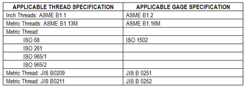
Determine which thread and gaging specification applies to the product being inspected.
ASME B1.2 1983, SECTION 5.2.1
The "NOT GO (LO) functional diameter is acceptable when the NOT GO (LO) thread ring gage applied to the product thread does not pass over more than three complete turns."
DEFINITION: Not Go ( Lo ) Thread Ring Gage
A Not Go or (Lo) thread ring gage inspects the Not Go or (Lo) functional diameter limit of product external thread. The Not Go thread ring gage, when properly set to its respective calibrated thread setting-plug, represents the Not Go (Lo) functional diameter limit of the product external thread. Not Go (Lo) thread ring gages must be set to the applicable truncated or Hi-Lo setting plugs.
DEFINITION: Not Go ( HI ) Thread Plug Gage
The Not Go (HI) thread plug gage inspects the Not Go (HI) functional diameter limit of product internal threads. The Not Go (HI) thread plug gage represents the Not Go (HI) functional diameter limit of the product internal thread.
ASME B1.1 Unified Inch Screw Threads
This standard specifies the thread form, series, class, allowance, tolerance, and designation for unified screw threads.
ASME B1.2 Gages and Gaging for Unified Inch Threads
This standard provides specifications and dimensions for the gages used on Unified Inch Screw Threads (UN Form) and covers the specifications and dimensions for the thread gages and measuring equipment.
ASME B1.13M METRIC SCREW THREADS M- PROFILE
This standard contains general metric standards for a 60 degree symmetrical screw thread with a basic ISO 68 profile designated M profile. The M profile threads of tolerance class 6H/6g are intended for metric applications where inch class 2B/2A have been used. At the minimum material limits, the 6H/6g results in a looser fit than the 2B/2A.
ASME B1.16M GAGES AND GAGING FOR METRIC M SCREW THREADS
This standard provides essential specifications and dimensions for the gages used on M series metric screw threads, and covers the specifications and dimensions for the thread gages and measuring equipment.
ASME B1.16M 1984, section 5.2.1
"LO Functional diameter limit is acceptable when the LO ( NO GO ) thread ring gage is applied to the product external thread if:"
It is not entered; or All complete product threads enter, only if a definite drag from contact with the product material results on or before the second turn of entry. After the drag is definite, the gage should not be forced after the drag is definite. In other words, the external thread that is made to the ASME B1.13 standard will fit the entire length of the NOT GO Ring gage can still be acceptable as long as the inspector can feel a "definite interference" between the gage and the thread not more than two threads from the starting end.
ISO 68 BASIC PROFILE
ISO 68 states that each thread is characterized by its major diameter and its pitch.
ISO 261
ISO 261 defines a detailed list of preferred combinations of outer diameters and pitch sizes for ISO metric screw threads.
ISO 1502-1996, section 7 (METRIC)
"A NOT GO screw ring gage, when screwed by hand without using excess force on the work piece thread, may enter on both sides by not more than two turns of thread."
JIS B 0251 & JIS B 0252, section 7.1.9 (METRIC)
"The NOT GO thread can not be screwed two revolutions or more."
JIS B 0209 & JIS B 0211 (METRIC) This standard specifies the fixed limit gages to be used for the dimensional inspection of metric screw threads
What action can be taken when two gages provide different results?
Case: Two identical NOT GO thread ring gages provide different results when inspecting parts. One gage exceeds the allowable entry onto the part while the other gage does not.
Solution: The gages must be evaluated and recalibrated by means of a setplug to see if the ring gages are set correctly to size. There are many factors that can cause a thread ring gage be out of tolerance. A gage may be accidently dropped by an operator causing the gage to be knocked out of size. Wear from use of the gage may be a factor prior to its frequency of calibration due date schedule. The two gages may be set to two different setplugs. Due to gage tolerance of the setplugs their actual sizes may be slightly different creating a different size and fit for the ring gages. Compounding this condition is the subjectivity of "drag" for setting thread ring gages to matching setplugs.
End Result: After the evaluation of both gages and if they meet the calibration requirements than they are considered acceptable. (SEE ASME B1.3, SECTION 6.B & ASME B1.2)
To reduce the possibility of a gaging dispute, manufactures of threaded product should not allow Not Go ring gages to enter more than 1 ½ to 2 turns.